
[MW:28452] Re: WELDER QUALIFICATION TEST RANGE


On Friday, October 19, 2018 at 4:27:35 PM UTC+5:30, ISHAAN wrote:
Dear Experts,

I would like to know what is the minimum range of Plate & Piping material (thickness, Pipe size) to qualify...??? ( Min. range to pass till max allowable thick dia of material)

Also I would like to Know that what are the steps to prepare PQR-WPS and what is Primary & Secondary document between them.
 
The answers to your questions are found in Section IX, Articles QW-452.1(b) and QW-461.9. 

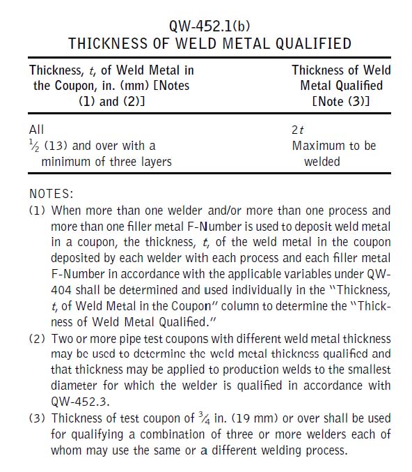
There is no minimum thickness qualified under ASME Section IX-2010 based on QW-452.1(b). The welder is qualified for a range up to 2t, where t is the thickness of the weld deposited if the weld deposited is less than 1/2 inch or less than three layer (not beads). The thickness range is unlimited if the thickness of the weld deposited is 1/2 inch or thicker and the welded sample consists of at least three layers. Your welder is qualified for unlimited thickness per QW-452.1(b) assuming at least three layers were deposited. 

As for the range of pipe diameters, that depends on the diameters of the pipe. There are two categories, pipe less than or equal to 24 inches in diameter and pipe over 24 inches in diameter. In your case the pipe is over 24 inches in diameter. QW-461.9 indicates the performance qualification done on plate in the 3G position qualifies the welder for the 1G and 3G pipe positions when the pipe is over 24 inches in diameter.
 

--
https://materials-welding.blogspot.com/
https://www.linkedin.com/groups/122787
---
You received this message because you are subscribed to the Google Groups "Materials & Welding" group.
To unsubscribe from this group and stop receiving emails from it, send an email to materials-welding+unsubscribe@googlegroups.com.
Visit this group at https://groups.google.com/group/materials-welding.
For more options, visit https://groups.google.com/d/optout.

Comments

Popular posts from this blog

Heat tint (temper) colours on stainless steel surfaces heated in air // Heat tint

Introduction The colour formed when stainless steel is heated, either in a furnace application or in the heat affected zone of welds, is dependent on several factors that are related to the oxidation resistance of the steel. The heat tint or temper colour formed is caused by the progressive thickening of the surface oxide layer and so, as temperature is increased, the colours change.   Oxidation resistance of stainless steels However, there are several factors that affect the degree of colour change and so there is no a single table of colour and temperature that represents all cases. The colours formed can only be used as an indication of the temperature to which the steel has been heated. Factors affecting the heat tint colours formed Steel composition The chromium content is the most important single factor affecting oxidation resistance. The higher the chromium, the more heat resistant the steel and so the development of the heat tint colou...

Materails FAQs

Q: What are equivalents for standard Q 235 B (and Q 235 A) for U-channels? (asked by: boris.vielhaber@vait.com) A: DIN Nr. = 2393 T.2, 2394 T.2, EN 10025 W. Nr. DIN 17007 = 1.0038 Design DIN 17006 = RSt 37-2, S235JRG2 (Fe 360 B) Q: What is St DIN 2391 BK material? (asked by: dmcandrews@automaticstamp.com) A: Precision steel tubes, cold-finished/hard. Q: What is C.D.W. Boiler Tube? (asked by: montydude123@yahoo.com) A: Cold Drawn Welded Boiler Tube. Q: WHAT IS W.Nr. 1.4301? PLS TELL US IN EASY LANGUAGUE (asked...

The Schaeffler and Delong diagrams for predicting ferrite levels in austenitic stainless steel welds

Introduction Ferrite is important in avoiding hot cracking in during cooling from welding of austenitic stainless steels. 'Constitution diagrams' are used to predict ferrite levels from the composition by comparing the effects of austenite and ferrite stabilising elements. The Schaeffler and Delong diagrams are the original methods of predicting the phase balances in austenitic stainless steel welds. Nickel and chromium equivalents A 'nickel equivalent' is calculated for the austenite stabilising elements and a 'chromium equivalent' ferrite stabilising elements. These are used as the axes for the diagrams, which show the compositional equivalent areas where the phases austenite, ferrite, martensite (and mixtures of these) should be present. Although intended to show the phase balance of weld fillers, these diagrams can also be used to illustrate the phase balance of the 'parent' material. There are different diagrams for dif...